It appears that your cart is currently empty


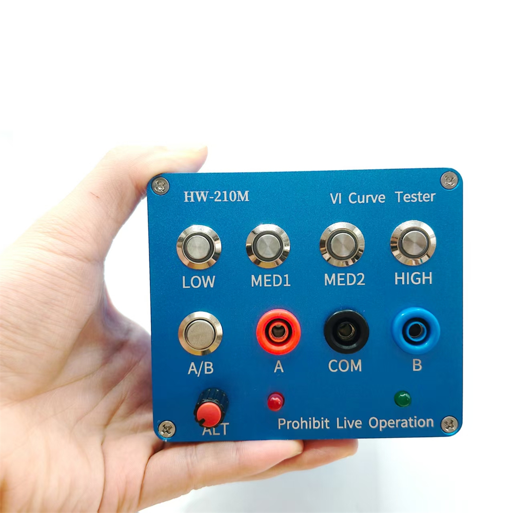
Features:
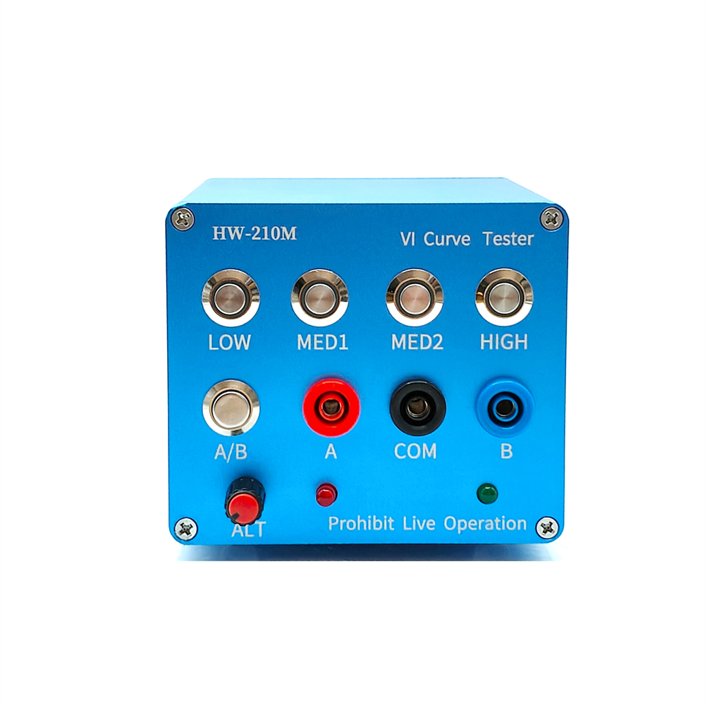
- Four test frequencies. (Usable when connected to an oscilloscope, both analog and digital)
- Dual signal input, alternating display
- Four frequency settings with adjustable AC speed
- Click single channel/alternating display
- Blue operation indicator for intuitive operation.
Specifications:
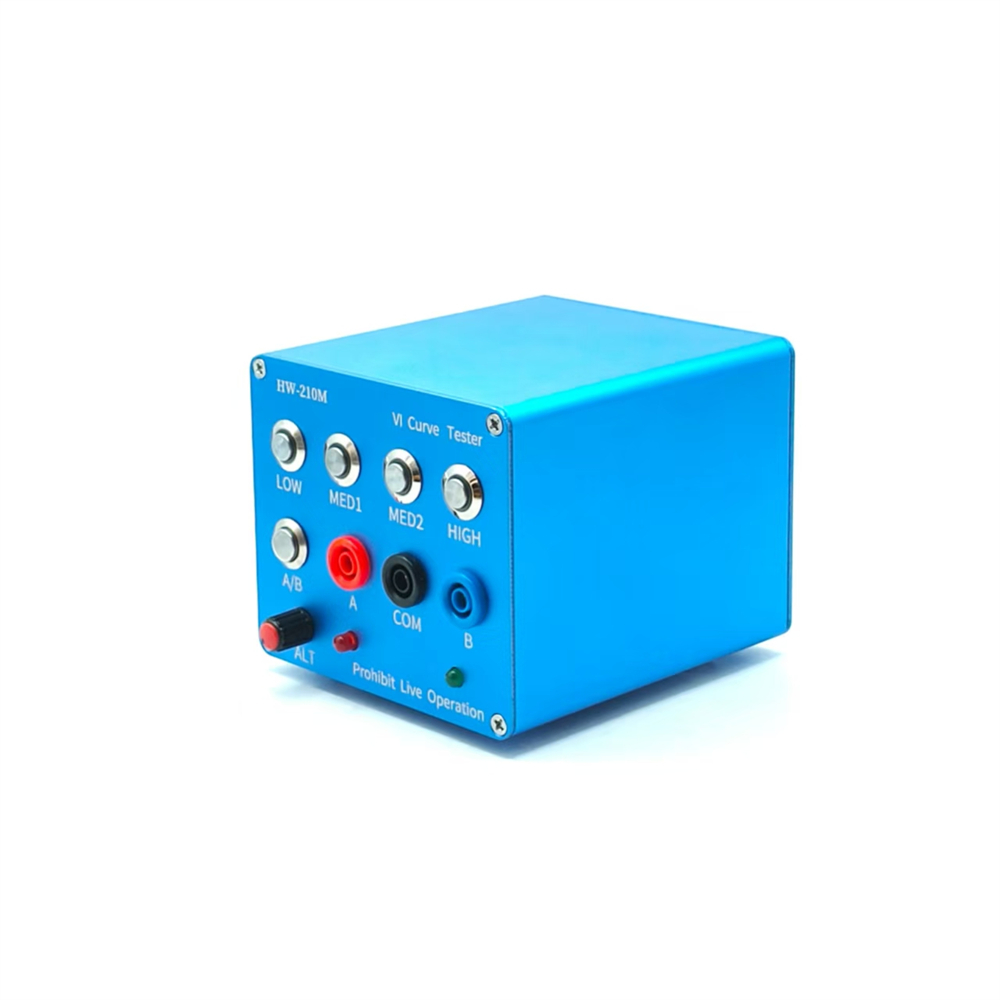
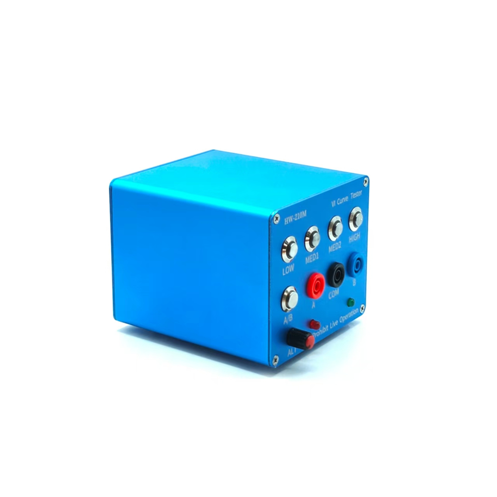
Case Material: Aluminum Alloy
Case Color: Sky Blue
Dimensions: 109.0*97.0*84.0mm
Volume: 114123.93mm³
Surface Area: 115840.41mm²
Weight: 385.16g
Case Length: 105.0mm
Number of Holes per Case: 14
Power Supply: 24V DC Power Adapter
Surface Finish: Sandblasted Oxidation
Package Included:
1 x Main Unit
2 x Test Leads
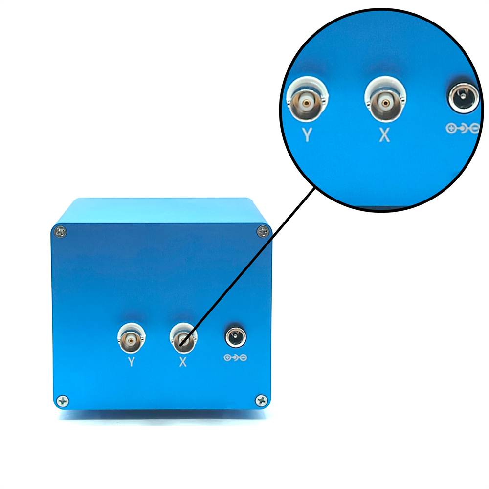
2 x BNC Cables
How to Use:
Oscilloscope Parameter Settings:
- Adjust the oscilloscope to X-Y mode (different oscilloscopes have different adjustment methods, please explore them yourself).
- Adjust the vertical parameters of both X-Y channels to 1V/div. Only one mono channel is required.
- Analog oscilloscopes do not require timebase adjustment; digital oscilloscopes have a timebase adjustment between 1 and 5ms.
- When properly connected, the oscilloscope will display a horizontal line. If a vertical line is displayed, the XY connector is inverted.
- Adjust the vertical and horizontal parameters. The horizontal and vertical lines are located in the display box. How to connect an analog oscilloscope:
Connecting an analog oscilloscope is relatively simple, but the process varies slightly depending on the oscilloscope.
Set the oscilloscope to xY mode. Some oscilloscopes allow you to select this mode by pressing a button, while others use the xY mode knob. Learn this yourself.
Connect a BNC cable to the oscilloscope and power it on. Normally, a horizontal line will be displayed. Adjust the xY vertical channel parameters to approximately 1V/div, then adjust the xY attenuation so that the horizontal line is within the display frame. You can also test the version using the VI. The upper x attenuation potentiometer can help adjust the length of the horizontal line. If the test probe is short-circuited, a vertical line will normally be displayed. If the vertical line is too long or too short, adjust the Y channel parameters to ensure that the vertical line appears within the display frame. Half a division or 1 division at the edge is ideal. If the horizontal and vertical lines are normal, you can enter the normal measurement values.
How to connect a digital oscilloscope:
For digital oscilloscopes, enter xY mode through the menu or key. Adjust both xY channels to 1V/div. For single-channel oscilloscopes, only the Y channel needs to be adjusted. Adjust the timebase to 1-5 milliseconds. Set the xY channels to DC coupling and the attenuation to 1x.
When the oscilloscope is not connected, the screen should be bright. Adjust the horizontal and vertical settings to center the bright spot. Connect the VI tester. Normally, it should be a horizontal line. Adjust the 103 potentiometer on the top of the VI board to form a horizontal line within the display frame. A shorted test lead of half a grid line or one grid line to the edge is a good starting point. The display should now be vertical. Adjust the Y channel parameters to keep the vertical line within the display frame. This concludes the debugging process.
When testing a circuit board online, do not charge the board. If there is a large capacitor on the board, discharge it first; otherwise, it can easily damage the VI test board.
Note: There may be color variations between batches, but this does not affect performance. Please do not purchase if you are concerned.