It appears that your cart is currently empty
Overview:
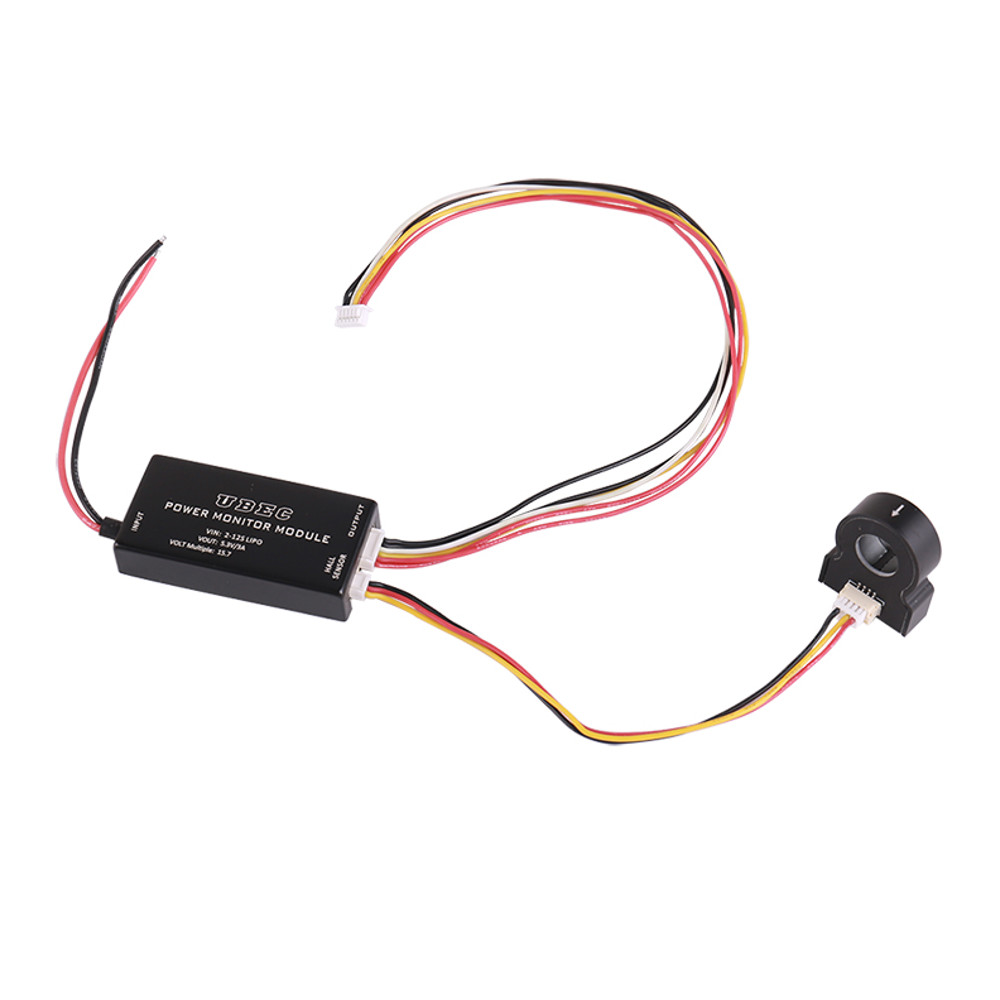
The Hall current and voltage meter adopts the separation design of the main module and the hall sensor. The main module provides UBEC 5.3v power supply and high-precision resistance 1 / 15.7 partial voltage output to detect the input power voltage function. The hall sensor is responsible for detecting the circuit current to be measured by non-contact induction. The hall sensor has built-in digital processing circuit and built-in reference, In addition, a variety of technologies such as piecewise linear correction algorithm, static monitoring algorithm, temperature detection compensation algorithm, PID closed-loop tracking output algorithm and other technologies are used to stably output a fixed ratio of analog voltage signal.
Compared with the traditional series in galvanometer, the biggest advantage of hall galvanometer is that it greatly improves the safety of the equipment. The series galvanometer needs to disconnect the circuit to be tested and connect a high-precision high-power voltage divider to detect. This method will add at least two solder joints to the current circuit, the contact resistance of solder joint and the dissipation heat of detection resistance, In the current circuit with dozens of a, it is a huge potential safety hazard. This kind of hidden trouble can be eliminated effectively by using Hall sensor.
Upgraded!!! The new hall galvanometer supports the main module and the hall module to be used independently without matching. The hall module can also be used for the modification of other ordinary galvanometers. It only needs to connect the 5V power supply, disconnect the current signal of the original galvanometer and connect the current signal of the hall module.
Specifications:
Brand Name: Mayatech
Item Name: Main Module with hall sensor
Hall Sensor Version: Universal interface, Lock interface (optional)
UBEC Main Module:
Input Voltage: 2s-12s lipo (max60v)
Output Voltage: 5.3V/3A
Partial Pressure detection: 15.7
Dimension: 25 * 51 * 10mm
Weight: 15g
Hall Sensor:
Power Supply Voltage: 5V(土0.3)
Detection Ratio: 60.61A/V
Detection Reference: 0.825V/50A
Dimension: 22 * 26 * 8.5mm
Threading Hole Diameter: 10mm
Installation Hole Distance: 17mm
Weight: 11g (there will be some errors in the manual measurement, and the actual object shall prevail.)
Note: Although the maximum input voltage of the main module can reach 60V, the detection voltage can only be about 51.8v on the main control of 3.3VADC system, that is, the voltage of 12s lithium battery; the hall sensor adopts 5V regulated power supply, otherwise the detection accuracy will be affected.
Hall Calibration Instructions:
The calibration of Hall sensor is divided into static calibration and ratio calibration. Static calibration refers to returning the output signal to zero when the input current is 0. Ratio calibration refers to setting the output signal at 0.825v under the condition of input standard 50A current, so as to fix the current ratio of Hall sensor as 50 / 0.825 = 60.61a/v.
The static calibration results will affect the ratio calibration results, so a static calibration must be conducted before the ratio calibration, and the static calibration only needs to meet the power supply of 5V and the current of 0, which can be calibrated at any time, and the result does not affect the ratio parameters.
Calibration Conditions:
1. Standard 5V power supply;
2.the standard 50A current source can be formed, which can be 5a, 10a, 25A, 50a, 5A. It is the way that the detection line is wound 9 times on the sensor to get a current source with 10 times current. 10A is wound 4 times and 25A is 1 circle. The more turns are wound, the greater the cumulative error is. Therefore, the 25 or 50A current source should be used as far as possible.
3. Connect the calib pin of Hall sensor to ground with a calibration switch (other methods that can provide low level can also be used)
Calibration Logic:
1. Static calibration: under the condition that the detection line current is 0, press the calibration switch twice in 3 seconds, or send two low-level pulses with an interval of more than 20ms in 3 seconds. The sensor will store the current hall static voltage data and pass through C_ Out pin output, then c_ Out scans step by step to reduce the output until the output signal is 0. After pressing the calibration switch twice, the current display slowly decreases from about 150A to 0A, and the static calibration is completed;
2. After static calibration, connect 50A current source and press the calibration switch for more than 3 seconds_ The output of out pin will slowly scan and rise from 0V to 0.825v. The result displayed on the detection terminal equipment (flight control) is that after pressing the calibration switch for 3 seconds, the current display slowly rises from about 0A to about 50A and is stable, and the ratio calibration is completed.
Package Included:
1x UBEC Main Module
1x Hall Sensor


