It appears that your cart is currently empty


Specifications:
Model: LC-Relay-ESP12-1R-D8
Color: Blue
Material: PCB
Work Voltage:DC8-80V/USB5V
WIFI IC: ESP8266
Communication Protocol:UART
Load Voltatge:AC 250V or DC 30V(Max)
Load Current:10A(Max)
Work Temperature:-25℃~85℃
Work Humidity:5%~95%RH
Features:
1. Onboard mature and stable ESP-12F WIFI module, large capacity 4M BYTE FLASH;
2. All I/O ports and UART program download ports of the WIFI module are led out to facilitate secondary development;
3. Support DC8-80V/USB5V/pin header power supply;
4. Onboard WIFI module RST reset button;
5. ESP-12F supports the use of development tools such as ECLIPSE/ARDUINOIDE, and provides reference programs under the ARDUINOs' development environment;
6. Onboard one 5V relay, output switch signal, suitable for controlling loads with working voltage within AC 250V/DC30V;
7. Onboard power indicator, 1 programmable LED and relay indicator.
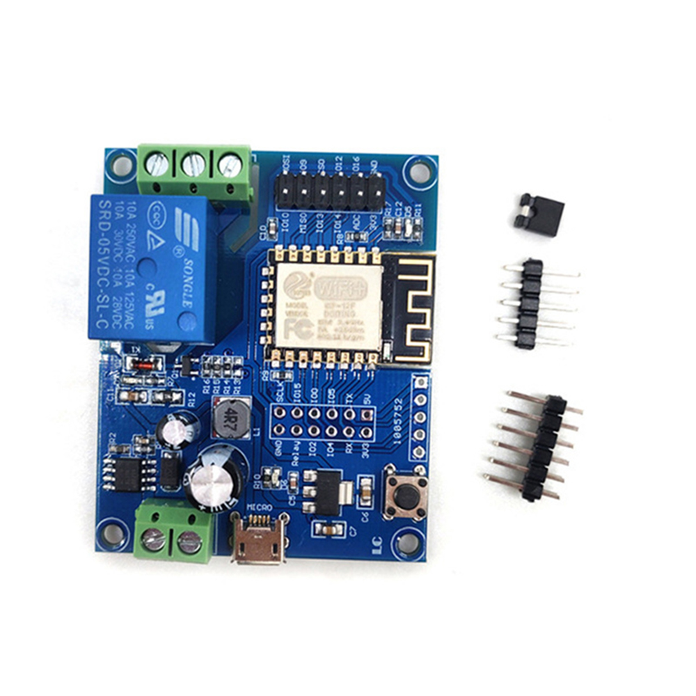
Package includes:
1 x DC 5-80V ESP8266 WiFi Single Channel Relay Module
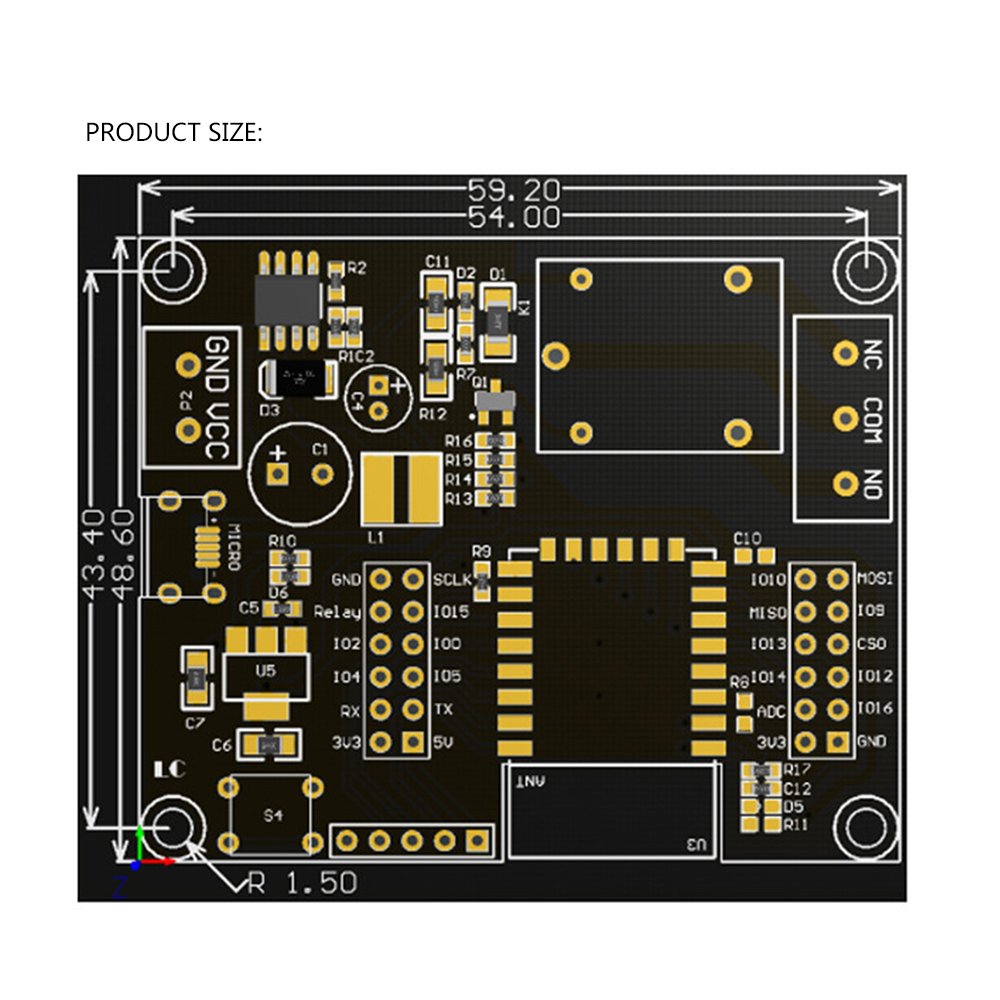
GPIO output port introduction:
| No. | Name | Function Description | No. | Name | Function Description |
| 1 | GND | Power ground | 13 | IO10 | GPIO10 |
| 2 | Relay | Relay drive port, IO5 is used as the default drive. If you want to use other I/O to drive the relay, you can remove R14 and then connect the I/O driving the relay to this Relay pin. | 14 | MISO | Slave output Master input |
| 3 | IO2 | GPIO2; UART1_TXD | 15 | IO13 | GPIO13; HSPI_M0SI; UART0_CTS |
| 4 | IO4 | GPIO4 | 16 | IO14 | GPIO14; HSPI_CLK |
| 5 | RX | UART0_RXD; GPIO3 | 17 | ADC | A/D conversion result. Input voltage range 0~1V, value range: 0~1024 |
| 6 | 3V3 | 3.3V power supply | 18 | 3V3 | 3.3V power supply |
| 7 | SCLK | Clock | 19 | M0SI | Host output Slave input |
| 8 | IO15 | GPIO15; MTDO; HSPICS; UARTO_RTS | 20 | IO9 | GPIO9 |
| 9 | IO0 | GPIO0 | 21 | CS0 | Chip select |
| 10 | IO5 | GPIO5 | 22 | IO12 | GPIO12; HSPI_MISO |
| 11 | TX | UART0_TXD; GPIO1 | 23 | IO16 | GPIO16 |
| 12 | 5V | 5V power supply | 24 | GND | Power ground |
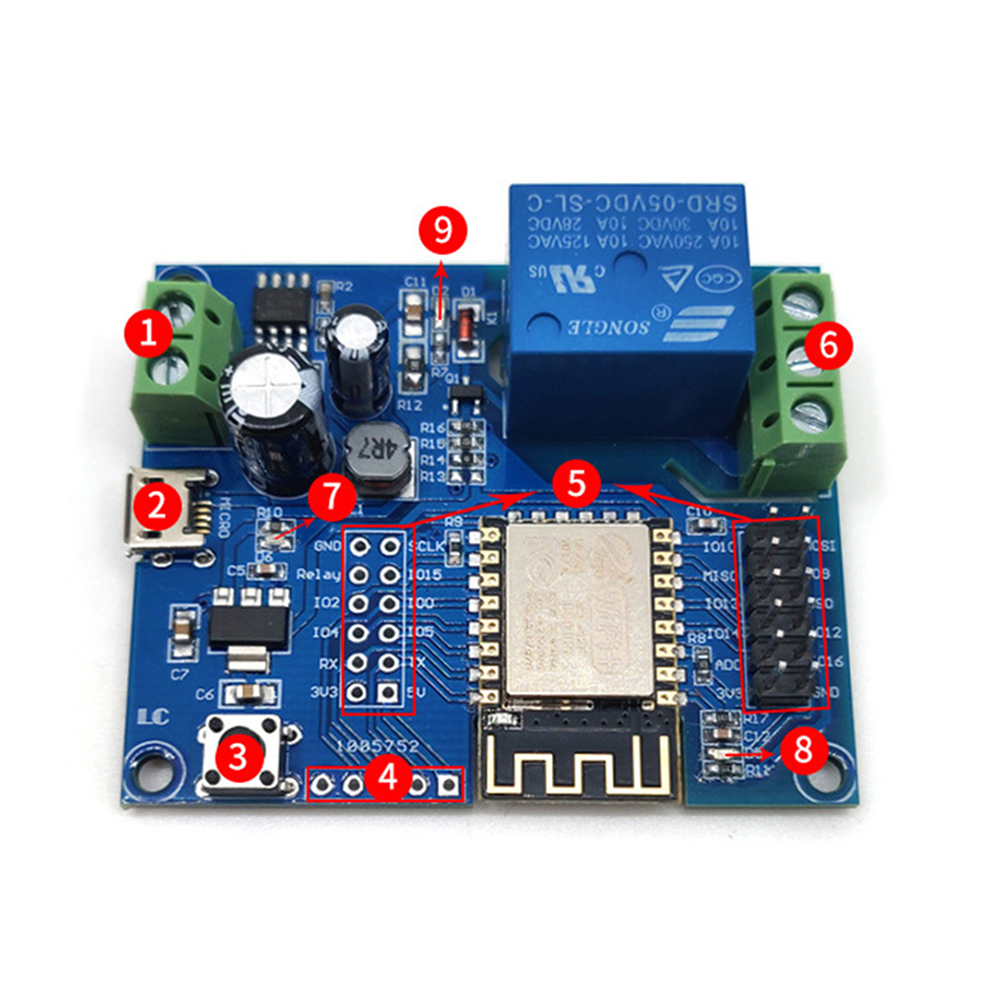
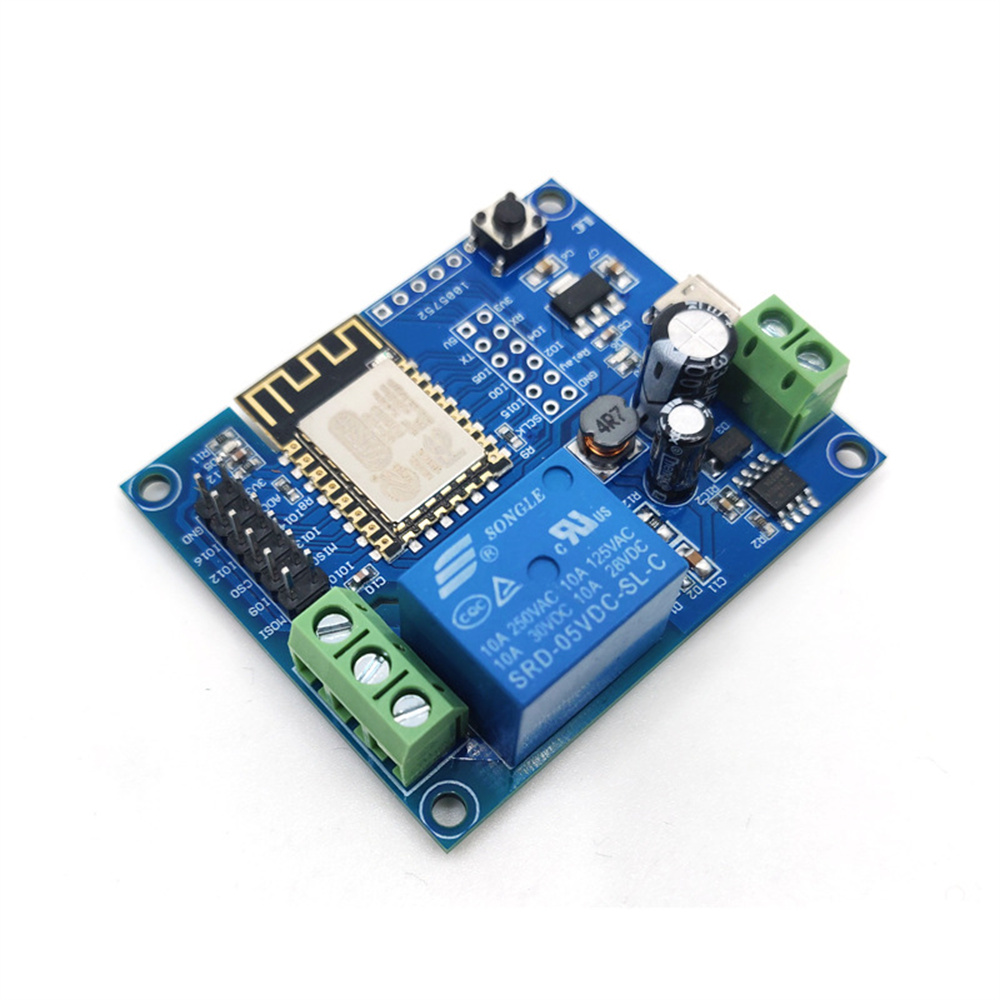
Port Locations:
① VCC, GND: DC8-80V power supply
② MICRO USB: DC5V USB power supply
Note: You can choose any of the three power supply methods: DC8-80V/DC5V USB/pin header 5V
③ 6X6MM button: ESP8266 reset button
④ UART program download port: ESP8266's GND, RX, TX, 5V are connected to the GND, TX, RX, 5V of the external TTL serial port module respectively. When downloading, I0O needs to be connected to GND. After the download is completed, disconnect the connection between IO0 and GND.
⑤ GPIO pin header lead port
⑥ Relay output terminal
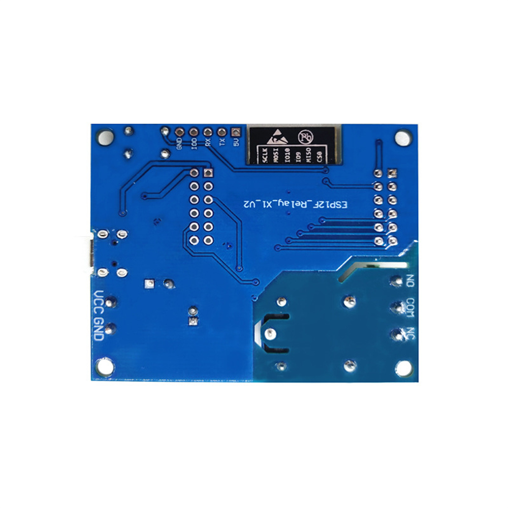
NC: Normally closed terminal, short-circuited with COM before the relay is energized, and left floating after energization;
COM: Common terminal;
NO: Normally open terminal, left floating before the relay is energized, and left short-circuited with COM after energization.
⑦ Power indicator LED
⑧ Programmable LED: controlled by GPIO16;
⑨ Relay indicator LED: lights up when energized.
Related product

HappyFish.co.za
LuckFox Pico Camera SC3336 3MP C...
Specifications:Sensor: SC3336Camera Type: ColorCMOS ...
R 446.13
Specifications:Sensor: SC3336Camera Type: ColorCMOS Size: 1/2.8'Pixel: 3MP (2304x1296)Shutter: Rolling shutterAperture: F2.0Distortion: <33%Focal Length: 3.95mmFocusing: Manu...

HappyFish.co.za
100K-6GHz Full Band Low Noise Am...
Description:The HT004 Low Noise Amplifier is an elec...
R 832.29 R 548.19
Description:The HT004 Low Noise Amplifier is an electronic device that is primarily used to amplify signals and minimize the effects of noise. It operates in the frequency range...

HappyFish.co.za
WZ3605E CNC DC Buck-Boost Conver...
Feature:>>>Manual: Click here to open<&l...
R 713.77 R 541.36
Feature:>>>Manual: Click here to open<<< Model WZ3605E Input voltage 6.0~36.00V Output voltage 0.60~36.00V Output current 0~5.000A Output po...

HappyFish.co.za
ESP32-S3 7 inch LCD Development ...
Specifications:- Microcontroller: Xtensa 32-bit LX7 ...
R 1,679.70
Specifications:- Microcontroller: Xtensa 32-bit LX7 dual-core processor, up to 240MHz- WiFi: 2.4GHz (802.11 b/g/n)- Bluetooth: Bluetooth 5 (LE)- SRAM: 512KB- ROM: 384KB- Flash M...

HappyFish.co.za
MMDVM Hotspot Spot Radio Station...
Description: Jumbo-SPOT-RTQ is a completely self-con...
R 2,369.70
Description: Jumbo-SPOT-RTQ is a completely self-contained digital hotspot supporting DMR, Dstar, P25 and System Fusion communications. Fully assembled and tested in a ruggedize...

HappyFish.co.za
Radioberry V2.0 Software Defined...
Description:1. The radioberry is actual a radio card...
R 4,379.70
Description:1. The radioberry is actual a radio card (raspberry pi hat), which can be plugged into a raspberry pi, forming a Software Defined Radio (SDR).2. The radio card uses ...